Logic Circuits (Cambridge International IGCSE Computer Science)
Exam board Cambridge International · IGCSEUpdated 2024-06-27
Spec point —
6.3.2· "3 (a) Use logic gates to create given logic circuits from a: (i) problem statement (ii) logic expression (iii) truth table"
Logic Circuits
What is a logic circuit?
- A logic circuit performs logical operations on binary information
- Logic gates are core components of logic circuits
- Based on the arrangement of logic gates and the input signals, the circuit performs a specific function
- A logic diagram is a visual representation of a combinations of logic gates within a logic circuit
- Brackets are used to clarify the order of operations
- An example logic diagram for the Boolean expression Q = NOT(A OR B) would be:
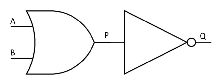
- In the logic diagram above, the inputs are represented by A and B
- P is the output of the OR gate on the left and becomes the input of the NOT gate
- Q is the final output of the logic circuit
Exam Hint You may be asked to draw a logic circuit from a logic statement or a Boolean expression OR write the logical expression that is expressed in the logic diagram using Boolean expression operators
Logic circuits will be limited to a maximum of three inputs and one output
Example of combining logic gates
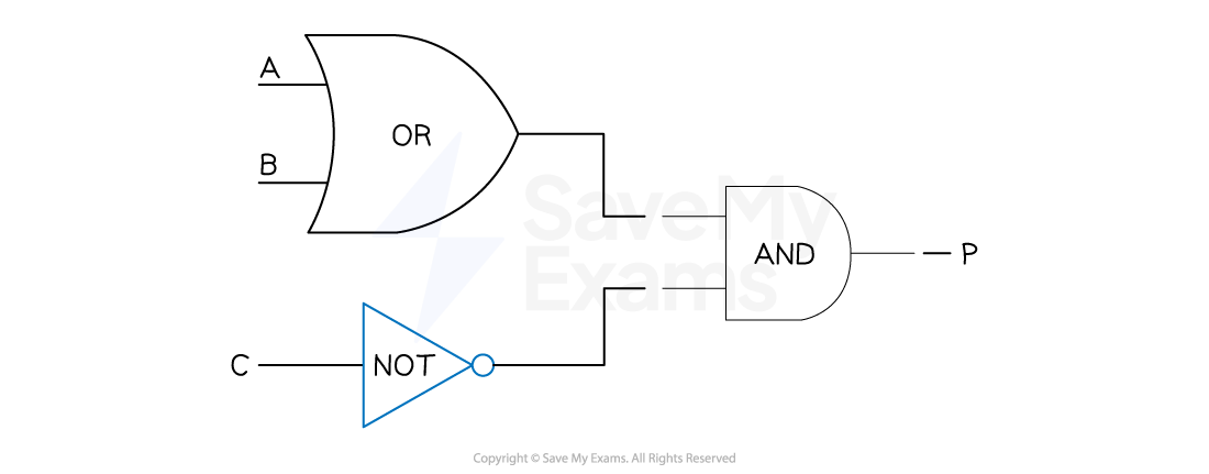
- P = (A OR B) AND NOT C
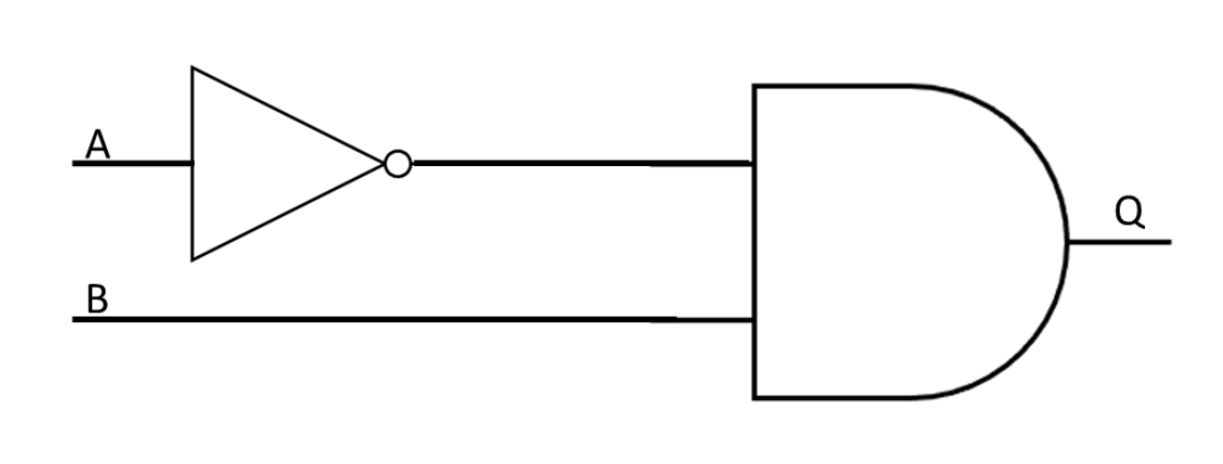
Worked Example A sprinkler system switches on if it is not daytime (input A) and the temperature is greater than 40 (input B)
Draw a logic circuit to represent the problem statement above
[2]
Was this revision note helpful?
Build on this topic