State-Transition Diagrams (Cambridge International AS Computer Science)
Exam board Cambridge International · ASUpdated 2025-09-03
Spec point —
12.2.2
State-Transition Diagrams
What are state-transition diagrams?
- A state-transition diagram shows how a system moves between different states based on inputs
- Each state represents a condition or situation of the system
- Transitions are arrows that show movement between states when certain inputs occur
- Transitions may also produce outputs, shown as labels on the arrows
- These diagrams model finite-state machines (FSMs), which are widely used in computing
Key elements
| Element | Description |
|---|---|
| State | Circle labelled with a name (e.g. S1, S2) showing a situation the system can be in |
| Initial state | Starting point, sometimes marked with an arrow pointing to it |
| Transition | Arrow from one state to another, labelled with input and output |
| Input | Event or data that causes a transition (e.g. Button-Y pressed) |
| Output | Action or signal produced by a transition (e.g. Output-A) |
| Next state | The state the system moves into after the transition |
How to read labels on transitions
- Labels are often written as Input | Output
- If no output is produced, “none” may be written
- Example:
Button-Y | Output-Bmeans pressing Button-Y in the current state produces Output-B and causes a transition to the next state - The diagram below shows the key features of a state-transition diagram:
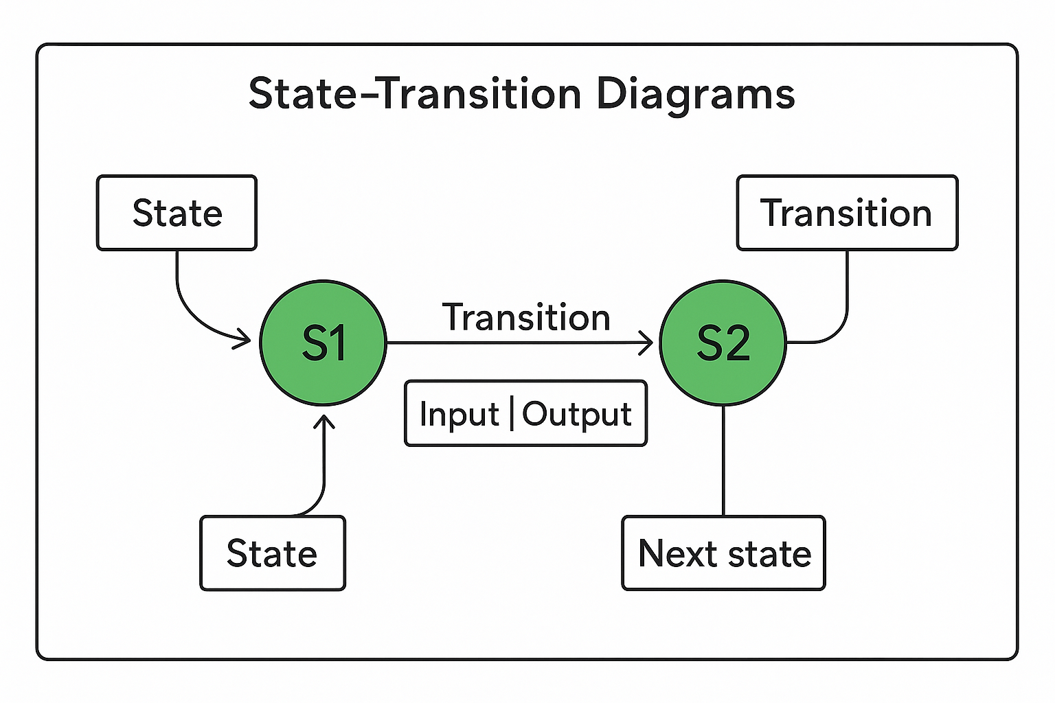
- States are circles labelled S1, S2, etc
- Transitions are arrows between states, labelled with Input | Output
- The initial state is marked with an incoming arrow
Completing transition tables
- Exam questions often ask you to convert a diagram into a table
- The table normally has columns for Current state, Input, Output, Next state
- Work through the diagram row by row, following the arrows for each possible input
Example table structure:
| Current state | Input | Output | Next state |
|---|---|---|---|
| S1 | Button-Y | Output-A | S2 |
| S1 | Button-Z | Output-B | S3 |
Exam Hint
- Always identify the initial state before tracing
- Highlight or mark inputs and outputs on your diagram to avoid missing one
- For tables, keep the order consistent: Input → Output → Next state
- Use arrows systematically, avoid guessing paths
- Remember: more than one sequence can sometimes reach the same state, but exams often ask for the minimum changes
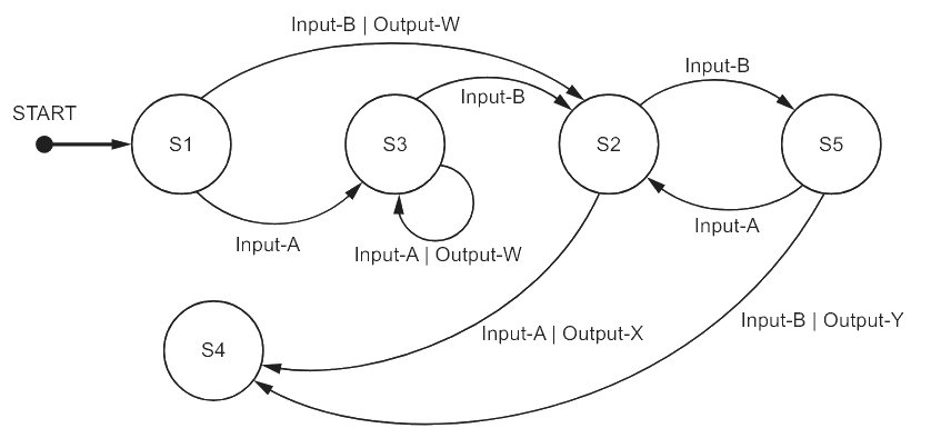
Worked Example Part of a program is represented by the following state‑transition diagram
A. Complete the table to show the inputs, outputs and next states.
Assume that the current state for each row is given by the ‘Next state’ on the previous row. For example, the first Input‑A is made when in state S1.
If there is no output for a given transition, then the output cell should contain ‘none’.
The first two rows have been completed.
Input Output Next state S1 Input-A none S3 Output-W none Input-B Input-A S4 [5]
B. Identify the input sequence that will cause the minimum number of state changes in the transition from S1 to S4
[1]
Final answer: Answers
A.
Input Output Next state S1 Input-A none S3 Input-A Output-W S3 Input-B none S2 Input-B none S5 Input-A none S2 Input-A Output-X S4
- One mark per row 3 to 7 [5 marks]
B. Input-B, Input-A [1 mark]
Was this revision note helpful?
Build on this topic