Fetch-Execute Cycle (Cambridge International AS Computer Science)
F-E stages
What is the fetch-execute cycle?
-
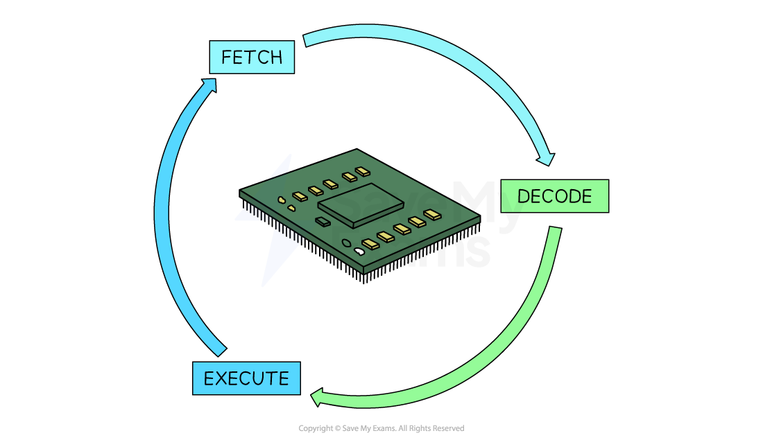
The fetch-execute cycle is the process that the CPU goes through repeatedly to process instructions
-
There are 3 stages:
- Fetching an instruction from memory - supplying the address and receiving the instruction from memory
- Decoding the instruction - interpreting the instruction and then reading and retrieving the required data from their addresses
- Executing the instruction - the CPU carries out the required action
How are registers used in the fetch-execute cycle?
-
In the section below, registers and CPU components appear in bold and assembly language is in italics
-
During the fetch-execute cycle, the following steps happen:
-
Fetch
- The PC is loaded with 0
- The value from the PC (0) is copied to the MAR
- The address in the MAR is sent via the address bus, and a read instruction is sent on the control bus
- The data from that memory location is sent down the data bus to the MDR
- The PC is incremented by 1, ready for the next instruction
-
Decode
- The data from the MDR is copied to the CIR
- The CIR splits the instruction into opcode and operand
- The instruction is sent to the CU, which decodes what to do next
-
Execute
-
The registers used will depend on the instruction:
- INP – value from input device is stored in the ACC
- OUT – value currently in the ACC is sent to the output
- LDA – loads value from RAM into the MDR, then to the ACC
- STA – takes the value from the ACC, moves it to the MDR, then stores it in RAM (location in MAR)
- ADD/SUB – value in RAM is loaded into the MDR, then the calculation happens in the ALU, result stored in the ACC
- BRA/BRZ/BRP – branching instructions are handled by the ALU to check if conditions are met, and the PC is updated accordingly
-
Register Transfer Notation (RTN)
- Register Transfer Notation (RTN) is a way of describing how data moves between registers in a CPU during the fetch–execute cycle
- It uses symbols to represent registers, and the arrow symbol ← to show data being transferred from one place to another
- It is a shorthand way to show what's happening inside the CPU
| Symbol | Meaning |
|---|---|
| ← | Data is transferred into a register |
| PC | Program Counter |
| MAR | Memory Address Register |
| MDR | Memory Data Register |
| CIR | Current Instruction Register |
| ACC | Accumulator |
| [ ] | Contents of a register |
| [[ ]] | Contents of the memory location addressed by the register |
Fetch
MAR ← [PC] ; Copy address from Program Counter to MAR
MDR ← [[MAR]] ; Read instruction from memory into MDR
PC ← [PC] + 1 ; Increment PC for the next instruction
CIR ← [MDR] ; Copy instruction from MDR to CIR
Decode
- No specific register transfer, the CU decodes the instruction in the CIR
Execute examples
- LDA X (Load value from memory location X into ACC):
MAR ← [operand] ; Load address X into MAR
MDR ← [[MAR]] ; Load data from RAM into MDR
ACC ← [MDR] ; Copy data into ACC
- STA X (Store value from ACC into memory location X):
MAR ← [operand] ; Load address X into MAR
MDR ← [ACC] ; Copy data from ACC to MDR
[[MAR]] ← [MDR] ; Store MDR value into memory
- ADD X (Add value from memory location X to ACC):
MAR ← [operand]
MDR ← [[MAR]]
ACC ← [ACC] + [MDR]
- BRZ X (Branch to X if ACC = 0):
If [ACC] = 0 then PC ← [operand]
Was this revision note helpful?
Build on this topic